Learning Objectives
- Learn about basic systems and characteristics of cube sats and Earth-based environmental monitoring stations.
- Learn how to operate an Arduino, upload and modify a simple program.
- Learn how to use a sensor operated by an Arduino and obtain data from it.
Introduction
Arduinos have been used to control a few cube sats such as ArduSat (now Spire), developed by ISU/SU Alumnus Peter Platzer. In fact, the ArduSat company can run experiments you develop on Earth using Arduino on actual cube sats in outer space.
Although Arduinos are not as powerful as Raspberry Pi computers or other dedicated controllers, they can perform the necessary tasks, and there is a lot less that can go wrong with them. (This is essential both in space and a 2-3 hour workshop!)
In Part I, we will learn how to set up an Arduino controller and read data from sensors. You should read the CubeSats page if you are unfamiliar with such.
Introduction to ArduinoSat
We will build an ArduinoSat, which is a prototype that contains several of the types of systems found on a CubeSat. It is called an ArduinoSat because it utilizes an Arduino prototyping platform. If an ArduinoSat is built according to ArduSat specifications, then some experiments developed for it can be uploaded to a real platform in space. However, our workshop ArduinoSat will be somewhat simple and different from an ArduSat.
Introduction to Arduinos
Arduino are a prototyping platform containing a controller, power regulation and other components.

Arduino Uno (credit: arduino.cc)
The Arduino requires a power source of 5 to 12 Volts. Initially, you should supply this with a special USB cable from your computer to the Arduino. This special USB cable can also be used for communications between your computer and the Arduino. Later, such as for field use, this can be supplied by a battery pack.
The Arduino must be programed to be useful. The Arduino Interactive Development Environment (IDE) comes with many programs. Such programs are called sketches, but may also be found under examples. You can also easily modify existing sketches or write your own.
Libraries are files that tell the Arduino how to communicate to particular devices such as sensors. To find the correct library, go to the source of the item requiring the library. Get the library and wiring data.
Setting Up and Testing An Arduino Prototyping Platform
Objective
To connect an Arduino Uno (or equivalent) to your computer, to communicate with it and send it a program.
Parts
You will need the following items:
- Laptop (or desktop) computer
- Arduino Uno prototyping platform
- USB cable to connect Arduino with computer (Type A to Type B) .
Getting Set Up
You need to start by downloading the Arduino Interactive Development Environment (IDE) on your computer. Then you will connect your Arduino to your computer. You will find and upload a simple sketch. Uploading a sketch will typically also start it to run. You should see a light blink on your Arduino. You will modify the sketch to learn a little bit of coding and also ensure that your computer really is communicating with the Arduino.
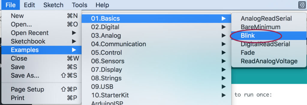
Blink sketch selected under hierarchy of File, Examples, 01.Basics in menu.
- Download the Arduino Interactive Development Environment (IDE) software: Arduino main software download.
- Open the Arduino IDE application (e.g. Arduino 1-6-5).
- Connect the Arduino to the computer using the USB cable.
- Open up the sketch Blink.
- Upload blink to the Arduino. Does the LED labels “L” blink? (If not, troubleshoot).
- Make a copy of the Blink sketch. Modify the timing. Can you change the timing of the blinking LED?
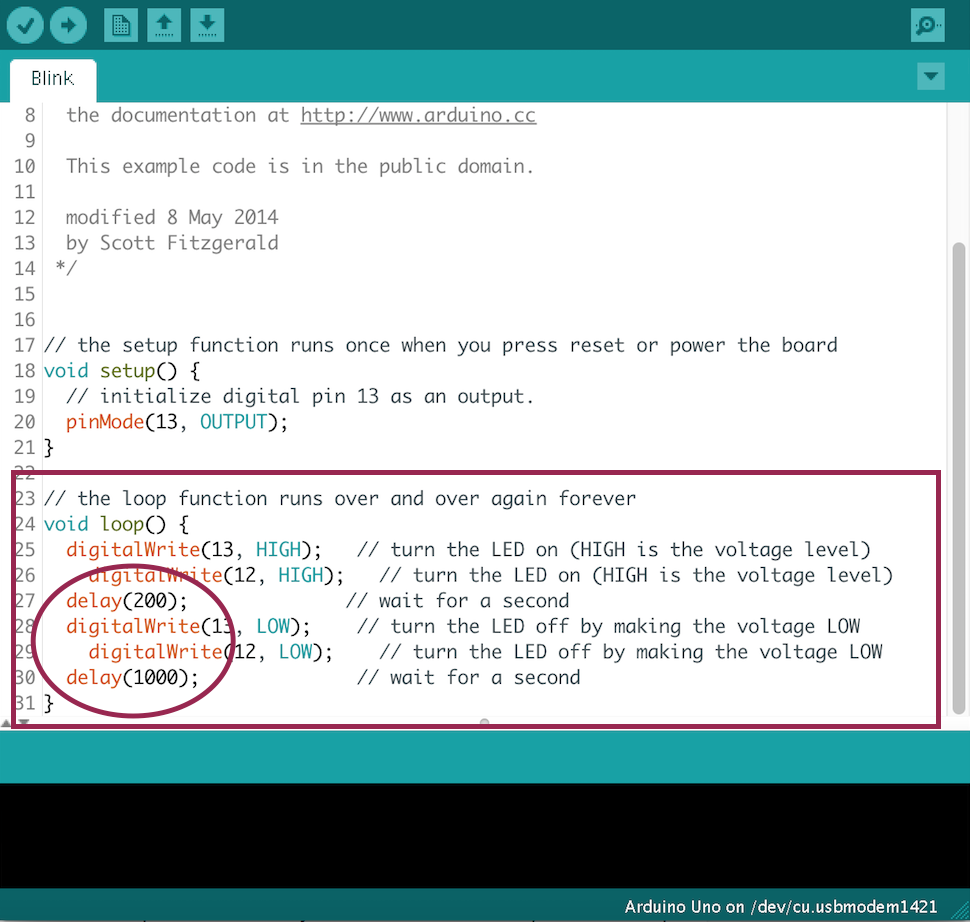
Loop and timing sections of Blink sketch
Hooking Up the Luminosity Sensor
(If you are familiar with Arduinos, you can skip this activity if you wish). Hooking up sensors is a key skill for Arduino systems. Here, we will hook up and read data from a luminosity sensor.
Parts
- All of above
- Half-breadboard
- Wires
- Luminosity sensor, e.g. Sparkfun 2561 or try here.
Tasks
- Find and download the Adafruit_Sensor library.
- Find and download the luminosity sensor library: Luminosity_TSL2561_Libraries
- If a sensor board is red, it is likely from Sparkfun. (See Sparkfun 2561 tutorial). It is it blue, it is likely from Adafruit. You may also need a general library from that source. Add the libraries to the Arduino IDE.
- Mount the luminosity sensor on the breadboard.
- Connect according to diagram on the vendor’s sensor reference page.
- Upload the sketch for the sensor (typically included when the library is imported).
- Open the serial monitor. Do you see the data flow?
- Alternative sensor? https://www.sparkfun.com/products/14350
Hooking Up The Inertial Measurement Unit (IMU)
The Inertial Measurement Unit (IMU) sensor contains gyroscopes that are functionally-similar to those in a satellite navigation system. It also contains a magnetometer and accelerometer. All of these are useful for a nanosat. For example, the magnetometer can detect the presence of magnetic fields such as those found in space. We will be using the ADAFRUIT DOF 9 or 10.
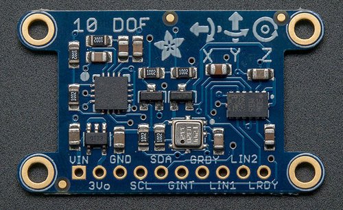
Adafruit 10-DOF IMU Breakout
10-DOF Sensors include:
- L3GD20 3-axis gyroscope: ±250, ±500, or ±2000 degree-per-second scale
- LSM303 3-axis compass: ±1.3 to ±8.1 gauss magnetic field scale
- LSM303 3-axis accelerometer: ±2g/±4g/±8g/±16g selectable scale
- BMP180 barometric pressure/temperature: -40 to 85 °C, 300 – 1100hPa range, 0.17m resolution
- Place an IMU sensor break-out board close to the edge of your half-breadboard (so you can fit additional boards).
- Open up the IMU sensor guide to tell you how to wire this sensor. Wire up the sensor as shown.
- Open the Arduino Interactive Development Environment (IDE)
- Install the required libraries found at the AdaFruit guide page (also listed below).
- Upload the Pitch and Roll sketch under Examples in the Arduino IDE file menu.
- Open up the Serial Monitor under the Tools menu.
- Choose 115200 or 38400 baud (or whatever works).
- Rock and roll the Inertial Measurement Unit. The readings on the serial monitor should reflect your actions.
Libraries:
- Adafruit_10DOF-master or Adafruit_9DOF-master
- Adafruit_Sensor-master
- Adafruit_LSM303DLHC-master
- Adafruit_L3GD20_U-master
- Adafruit_BMP085_Unified-master
- Adafruit wire.h
Troubleshooting
(Try any of the following as needed):
- Check the port and board selections in the Arduino IDE.
- Check the connections.
- Restart the IDE.
- Restart your computer.
- Replace the wires.
- Replace the components.
Getting Your Own Arduino
Although there are many varieties of Arduinos, it is recommended to start with an Arduino Uno made by a reputable source. Many of the other varieties such as an Nano or Micro don’t have as many connectors or communications ports. However, you may prefer to use those once you know what your are doing.
There are many sources of Arduinos. Again, I recommend that you get them from a reputable source, such as arduino.cc. Some of the Arduinos sold by third parties (even Amazon) are counterfeits or cheap versions prone to malfunctions, regardless of who Amazon states the real supplier is.
Reliable sources of Arduino (not a comprehensive list):
- Arduino.cc
- Sparkfun
- Adafruit
- Sometimes not Amazon!
Disclaimer
Although SustainSat is not affiliated with ArduSat, it is recommended that readers consider their educational platforms and space services.